Running the Line Impedance Test
Line impedance testing for FXO interfaces is done using the AnalogLineTest command through the device's Command Shell. The command runs the line test on a specified channel and for every specified impedance level (configured by a range), and then saves the results.
Before performing the line impedance test, you must upload a Voice Prompt file to the device.
|
➢
|
To run the line impedance test: |
|
1.
|
Access the device's Command Shell, which is done by appending "FAE" to the device's IP address in your Web browser's URL (e.g., http://10.13.4.13/FAE), and then clicking the Cmd Shell option located in the left pane. |
|
2.
|
On the command-line prompt, enter the AnalogLineTest command in the following format: |
AnalogLineTest <FXO Channel> <Impedance Low Limit> <Impedance High Limit> <Display Syslog>
Where:
|
●
|
<FXO Channel>: FXO channel that you want to test and configure. |
|
●
|
<Impedance Low limit>: Low level impedance value (0-15) that you want to test |
|
●
|
<Impedance High limit>: High level impedance value (0-15) that you want to test |
|
●
|
<Display Syslog>: Defines (0/1) if information is sent to syslog during the test |
The following example runs the test on FXO channel 4 with impedance levels 0 to 5 and sends the output to syslog (1):
>/VoiceEngn/AnalogLineTest>AnalogLineTest 4 0 5 1
Starting......
Check syslog for more information.
This command starts a test on channel 4.
Impedances 0-5 will be tested.
Messages are displayed in syslog during the test.
The following describes the sequence of events when you run the impedance matching test:
|
3.
|
The test is run using the AnalogLineTest command. |
|
4.
|
The tested channel is opened with default parameters and set to off-hook state. |
|
5.
|
The channel is configured with the low level impedance value. |
|
6.
|
A call involving the channel is started. |
|
7.
|
A PCM Voice Prompt file is played in the TDM direction. |
|
8.
|
The returned echo is recorded in a second PCM file. |
|
9.
|
Both of these files are scanned simultaneously and an ERL value is obtained. |
|
10.
|
The above steps are repeated for each of the specified impedance levels. |
|
11.
|
When the test completes, the channel is on-hooked and closed. |
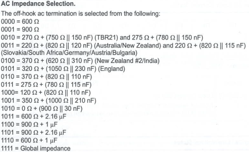
The figure below shows the correlation between the impedance values in binary (0-15) and the actual impedance values (Ohms).